What's new

Upgrading the Accord iCDTi ICE. Many Questions (& hopefully Answers too!)

Managed to do a bit more work on the install on Monday. Firstly there was "Upgrading the Big Three"

OE car wiring is built down to a price, and is also built to a certain spec. Car manufacturers will build to a price point/standard, but if you imagine how much wiring they put into every car, even small savings of a few pence add up to millions of £££'s over time. Copper cable is expensive, the thicker the cable, the higher the cost per foot/metre. Cars are not designed to have aftermarket goodies added to them

Take the earth straps in your engine bay, they do an important job if engine/gearbox to chassis & battery to chassis. If you have ever had earthing issues of one form of another, you will already know how important a solid earth is to the cars electrical system. Bad earths can lead to all sorts of malfunctions, one of the most common is radio interference, or rear light clusters going crazy.

Over a period of time copper oxidises in contact with air causing it to corrode, also after many years of vibration wires can also fatigue. They may not totally break, but fatigue or corrosion can cause the performance of the cable to become severely compromised as time passes.

This can cause loss in your electrical systems efficiency, the battery might not get as much charge as it should, the starter might not get as much current as it should so turns slower causing it to take longer to start, the spark plugs could get a weaker high voltage (more so in older cars but you get the idea)....

The really important earths are Engine/Battery Engine/Chassis & Battery/Chassis. There are lots more but for simplicity sake we won't name every single one. By either replacing these earths, or adding additional earth cables in these distinct areas, the theory is you will help to bring your cars electrical earths back up to or even better than (more of this later) it was when it left the factory. When you install a kit like this an essential is a small wire brush to take off any corrosion back to bare metal, or if a supplementary earth, to take paint off back to bare metal. Obviously you don't do this where rust would result etc.

In ICE thinking, "The Big Three" takes this a stage further than just upgrading your ground cables.

Additionally upgrade or replace entirely......
1) Battery Ground to Chassis
2) Battery Ground to Engine/Gearbox
3) Alternator to Battery Positive

In ICE, especially at the performance/competition end, an efficient electrical system across the board is essential, but as a first stage the Big Three is normally a first step to gaining better performance/efficiency. BEFORE adding more batteries or capacitors or bigger rated alternators etc. so get the best out of what you have FIRST, before spending additional funds where it might not be otherwise necessary. So using as big a cable you can afford & that will fit (4awg is a decent starting point in ICE terms, rising to 0awg or bigger for big ICE), run supplementary cables in these vital areas to improve performance. The difference is quite marked. I did the big three on my Honda on Monday, 13.8 was across the battery at idle, it is now 14.11. Proof in my own eyes that the theory works in practice.

Way back on my Lexus I did notice marginally better starting (& it wasn't a bad starter to begin with) and a smoother idle. I also got better Radio reception than previously. On the Honda the idle seems smoother too, but maybe that is my mind playing tricks on me. I hope what I have posted makes sense, I'm no expert/professional but have tried to explain the theory as best I can after years doing ICE as a hobby & all information is correct as I understand it.

It was damn hard work continuing the install, as has everything else ICE related been with this car, but think we are turning a corner now. I forsee only one problem regarding getting additional wiring into each door, but I will cross that bridge when i come to it. Anyway here are the pics.

1 Remove Stock Battery & then the undertray to give better access for running the Alternator cable
1RemoveStockBattery.jpg


2 Oawg and Braiding
2OawgandBraiding.jpg


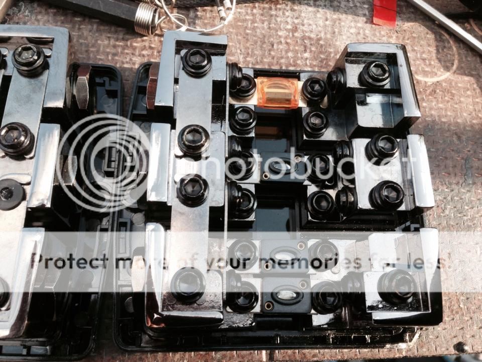
3 Battery Terminal and Chassis Earth Upgrade
3BatteryTerminalandChassisEarthUpgrade.jpg


4 I'm not a pro but that will do
4Imnotaprobutthatwilldo.jpg


5 O gauge & Conduit for Alternator & under the car
5OgaugeampConduit.jpg


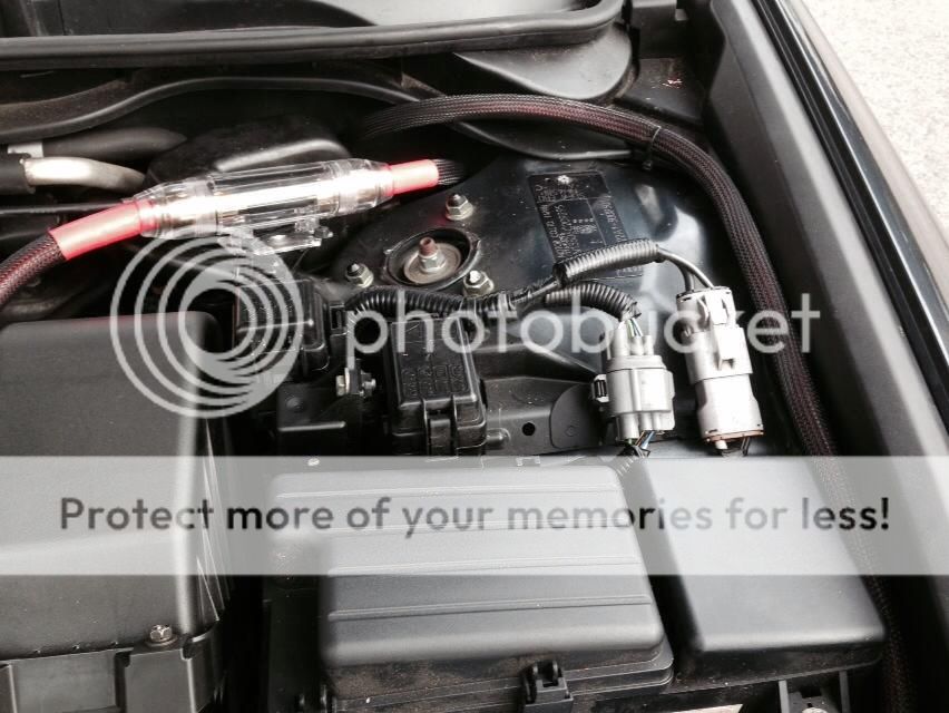
6 Extra Alternator Lead to Battery. The 0awg ring terminal was slightly oversize to fit on the stock alternator, so had to have a little dremel work so it fitted snugly.
6ExtraAlternatorLeadtoBattery.jpg


7 Alternator Lead in conduit
7AlternatorLeadinconduit.jpg


8 Insulated bracket spur to avoid chaffing of Power lead.
This is at the side of the engine cover, and would otherwise chaffe the Power Cable over time.
8InsulatedbracketspurtoavoidchaffingofPowerlead.jpg


9 Conduit Heatshrunk to Braiding
9ConduitHeatshrunktoBraiding.jpg


10 Positive Terminal
10PositiveTerminal.jpg
 
Continued/

11 Negative terminal inc main chassis ground to bolt head on right
11Negativeterminalincchassisground.jpg


12 Positive & Negative Cables
12PositiveampNegatiiveCables.jpg


13 Positive & Negative Cables Close up. They are routed down the back of the bulkhead into conduit, away from anything moving or very hot like the exhaust etc. The main fuse & all cabling are secured with cable ties.
13PositiveampNegatiiveCablesCloseup.jpg


14 Holes drilled for conduit entry into boot. Other places with existing grommets etc were investigated, but would hacve meant running the cables close to the RCA signal leads, so this was really the only alternative solution.
14Holesdrilled.jpg


15 Painted to avoid corrosion
15Paintedtoavoidcorrosion.jpg


16 view from underneath
16viewfromunderneath.jpg


17 Very snug fit cables into boot
17Verysnugfitcablesintoboot.jpg


18 Routing cables under the car
18Routingcablesunderthecar.jpg


19 Routing cables under the car
19Routingcablesunderthecar.jpg


As it was getting dark I took the pics under the car before the final tighten up, & all the ties had the lose ends clipped off.


20 0awg Ground Block & Fused Distribution Block (for the next stage of work next week)

200awgGroundBlockampFusedDistributionBlock.jpg


21 0awg Fused Distribution Block Close Up
210awgFusedDistributionBlock.jpg


What is going where you might ask?
Bottom Right - Fused Input from Front Battery 2x100A fuses.
Bottom Left - Input from Boot Battery
Top Right - 40A Fused Output for 300/1 Amplifier
Middle Right - 100A Fused Output for 1000/1 Amplifier

The bottom row allows both batteries to join their power together before it is distributed between the 2 Amplifiers. This way the entire left side is live as well so power is in a big L shape, then the top and middle right carry the fused power out to the two Amplifiers. Also the bottom two fuses give protection from the second battery should the Powercable under the car get damaged and will not allow the cable to remain live under the car. The Cable is protected at the other end by the fuse in the engine bay.

Next week there will be a big push with at least 2 more full days on the install, in a effort to ensure the car is finished well before JAE in September. Still to do? Well the list is long, but I am confident that we will have the car near completion by the end of next week, or at least in a position that it is all playing etc, with just some cosmetic touches to finish it of etc.
 
Looks really good man. Expensive, high grade electrical cabling always excites the nerd in me. I love this stuff. Is running the cabling under the car like the usual done thing? Is it ok being there with zip ties, close to the exhaust long term?
 
It was pretty much a last resort Steve. In ALL my previous cars there has been ample (& accessible) space in the sills under the doors to run cables, even fairly chunky ones like I have. This is the best install I have ever done, and have gone all out (within my budget) to do the best install I possibly can with this car. That meant this time instead of just running a single Power cable to the boot & use a point in the boot to earth to the chassis, I would run a full length Earth cable as well. The ICE thinking behind this is no eddy currents to provide interference to signal or speaker cables as the two cables so close together will cancel each other out.

The zip ties that I have used are fairly wide (about 12-15mm) so won't cause any stress on the conduit flutes, and the conduit itself was from an electrical cable company & is heat resistant. The cable is well away from the exhaust and I have every faith there will be no issues with it there unless I decide to hammer speed bumps, which I just don't do. The body skirts on the car sides are lower than the cables/conduit at it's lowest point.

I did make a small concession in the budget re the earth cable, My Red 0awg Power Cable was already bought. There was a 15m reel available of Red 0awg for a bargain price, so I am actually running a red Earth Cable, but it is entirely Braided and marked, plus it is a different brand of cable, so there is no chance in mixing them up as the manufacturer details are plastered along the lengths. Also the Positive Cable is routed furthest towards the side of the car, so from front to back, i can tell which is the Power Cable at a glance. The purist or the professional will shake their head, but tbh the price was too good to be true, and approx £50-60 for another full run of earth cable vs a one off end of stock £40 for 15m reel was a no brainer bargain I can certainly live with!!
 
Sounds good mate. Sounds like you've got things more than covered, above and beyond really. I bet you can't wait for it to all be finished.
 
very impressed with your install. Some serious effort put in to this. I wouldn't normally do a wiring job like that going under the car. Any reason why you haven't routed through the car?

Can't wait to see your end product
 
Thanks TypeR, post #95 answers the cable question I think.

My own expectations are pretty high now, & although the car is not built in anyway to be entered for competitions, it should be able to scare a few in the Sound Quality sector. I deliberately avoided doing door builds with multiple speakers as they attract too much unwanted attention, so pretty stealthy as from outside the car the Head Unit is really the only clue or the Alpine Freeview Aerials in the screen etc. The other thing I personally find about cars that compete in SPL Competitions (Sound Pressure Level) is the Stereo imaging tends to get very very very confused, or they have ridiculous amounts of bass to reach a high dB count, but they have very little balance for the rest of the audible frequencies. Let me explain what I mean, & please excuse the possible patronising explanation.

Audio Snobbery or Hi-Fi vs Loud Music Noise....

Hi-Fi
Take sitting in the middle of your sofa, ideally your floor standing or stand mounted speakers are about 4-6 feet in front of you, a similar equal distance apart, & are toe'd in slightly towards your perfect listening position. If your Hi-Fi system is any good, this set up 'should' give you an amazing stereo image of your favourite music. If the source material is good & the studio production/sound engineer did a good job, you should be able to hear (with your eyes closed) the singer in the middle directly ahead, & be able to pick out in front of you exact instruments in different places in the 180° forward of your listening position. Just like being in the front row of an orchestral concert for example. Being able to pick out individual instruments & where they are is an audio image making up the "soundstage". The wider & more accurate the soundstage, the more you should be drawn into the music. Try it & see what I mean.

The sound engineer has a massively important job in recreating the soundstage so it is as accurate as possible in the case of an orchestra, or in a much smaller case the artist & musicians etc. to give you a good stereo image, or to generate one to fool your ears into hearing one, as instruments can be recorded in different sessions (even on different continents) or be computer generated in much modern dance music.

So we have a good source CD player for example, quality amplifier, speaker location, separation, & listening position, we have a sound engineer in the studio mixing all the sources together to give us a wide soundstage with good imaging. This is Hi-Fi.

To recreate (as best as possible) the same audio quality in a car is a nigh on impossible task. The physics of momentum, constant vibration, unwanted noise, plus the physical size restrictions in the car mean speakers 4-6 feet away equidistant is NEVER going to happen. Compromises have to be made, but the task from my point of view is to get audio as close as possible to true Hi-Fi as I can, but to be able to go appreciably loud at the same time. That is my personal target for this install. Hi-Fi that has some real balls behind it, yet retaining the quality throughout. I removed the 6x9's on my rear shelf for two reasons. Firstly, the rear doors have speakers in them & as people in the back of my car are never as important audio wise as those in the front, the door speakers will be enough. Also I never understood why people rave about booming 6x9's, as when you go to a concert, all the main speakers are in front of you! Hi-Fi vs Noise again.... Secondly, once removed, they make great apertures to allow bass into the cabin.


Ideally as the main speaker set at the front, the Woofer (mid bass to upper mid freq) & Tweeter (lower high to highest freq) should be close together like home speakers. This ensures the path length from either speaker is approx the same distance to your ears on each side. Differences in path length alter how long it takes for the output to reach your ears can affect the timing, get the timing out & the music will start to become confused & muddled. This can be corrected by time alignment adjustment for each individual speaker to ensure the music reaches your ears at exactly the right time. By using the stock locations, my install is a compromise, but when adjusted shouldn't be much of an issue as the driver quality is very high as is the amplification & head unit.

Loud Noise
Cars going for big dB tend to go for massive numbers of drivers. In the doors, in the dash, in the roof, on the rear shelf etc. We have all heard little Johnny Chav in his Saxo parked outside Tescos with some ridiculously cheap but hugely loud 6x9's on his back shelf & a huge subwoofer & box taking up his entire boot. Take that kinda thinking & multiply it a few times & you get the SPL boys. Some have a bit more to them than that, but most are designed to ram as many speakers as possible into a vehicle to create as much sound as possible. A stack of mids & tweeters with subwoofers in huge enclosures with specifically designed ports that boost at a certain frequency to make the biggest reading on a dB meter is all very well, but it ain't Hi-Fi!! With all the different mids & tweeters you have sound coming at you from all directions, with different path lengths, the imaging tends to be all over the place, & it's fine if you want to make a girls hair move for a YouTube clip, but not a lot of use for anything else IMO. It's just musical Noise.

So my target is the best sound quality I can, with some real balls behind it. Fingers crossed eh?
 
Some pics of today's work Silent Coat-ing the boot. It's 95% completed, but constant rain interruptions & then failing light put paid to efforts until tomorrow, when I will remember to take better pictures. To apply this stuff correctly takes way way longer than you would think.

Stripped out boot


After pic


Some thorough side panel deadening. Double skins prevent as much covering as I would like but no choice, so it's just do the best we can...


CCF Foam used to decouple one panel from another, smaller pieces on the V spar front behind the rear seat (with Silent Coat behind on both sides & more CCF on the rear)


The metal boot slam panel is already covered in Silent Coat, CCF used again to dampen vibration, this time on the plastic slam panel cover


Pray for good weather Tuesday & Wednesday!!
 
Finished the Silent Coat in the boot yesterday. This really is becoming a chore now, but I can't take short cuts now after all this effort, but started to run low so I had to order some more. We are up to approx £350 just on sound deadening of different types, but thankfully it will be the last pack I need.

Then I made a hidden Battery stand as where the second battery was going to go, so it will be safe & secure Unfortunately, the floor was not flat. Much measuring, router, test fit etc took a fair bit of time. This was bolted down under the boot trim, then I had to make the board to mount the distribution Fuse Blocks on.

As it is a complex shape a template for one side was drawn, trimmed, trimmed some more etc. then again for the other half. Tape them together, trace out into MDF. Then ALL the sides needed to be beveled & contoured so it sank perfectly into the space, rather than 18mm square edges of the MDF poking out. Another age sanding & test fitting, then repeat until it fitted properly.

Next stage planning the Fuse cabling & Battery cables. I have decided to mount the battery backwards so the cables & terminals will be hidden. I test fitted it the other way round & it just oiled messy with too many cables on display. Hopefully the reverse mounting solution will be a bit tidier.

The Power Distribution Block & Ground Block were test fitted, final cable routes planned out, & the relevant cable holes drilled & chamfered & finally a quick squirt of paint. All of a sudden it was 7:30pm & time to call it a night. 3 rain interruptions have put tomorrow's hopeful finishing deadline out of reach.

The trimming carpet should arrive first thing, then I can crack on with completing the boot build, including finishing the box, amp rack, & re-installing the Subwoofer. That will then leave just 1 full day to deaden the doors, & install the speakers, & finally the head unit. Unsure when that will be as my pal is back at work on Thursday, so the delay till the final day of the install will be a real killer. After tomorrow tho, we will really be getting close.....so long as the carpet turns up this morning first thing!!

Anyway here is some pictures of yesterday's work.


The layer of black CCF Foam on the back of the V beam.


Battery MDF Routered base board under construction


Boot Slam panel deadening which will have the CCF Foam plastic trim panel applied when the boot is finished


Cardboard Template


Fuse Board


Fuse & Ground Blocks
Note the penciled wiring diagram as a reminder what cable is for each hole


Dab of paint round the holes


I'm sitting here praying for the carpet to arrive early...
 
Gonna finish the box today, install the Subwoofer, Perspex Window, make "beauty boards" (panels covering up cables etc) & an MDF mount for the Audio Control Epicenter. Would be good if the carpet turns up, but as yet no sign. Trip round the Docs first for my daily injection, then a trip home to check for deliveries, then off to my pals back garden for another full day (weather permitting).
 
Thanks Rich!!

Well the carpet didn't arrive, but the last pack of Silent Coat did arrive.... when I was out. It kinda sums up my day yesterday. Two steps forward & four back. It seems EVERY little job on this install has been a mare, either in getting things to fit, or having to make compromises I really don't want to.

I'm a bit down as I was hoping to get the car to a point where it is 95% done by this weekend, with just some cosmetic finishing off, but alas we have come up short. Everytime I guesstimate how long we have left, it seems I have to add two full days to it. So here is where we are after 3 full long days work this week...

The Box
I originally built this two years ago. It was designed to be installed on my Supercharged Lexus IS200 firing directly through the ski hatch. The complex folded port was so you could see the Subwoofer through the Acrylic window as per my previous install in that car. I spent a lot of time building that box, & it is ported & tuned to be twinned with the JL Audio 12W7 Subwoofer.


Getting everything together for a final plan out of the components


We were toying with the idea of using a larger lid extending backwards as an amp rack, but after a test fit jiggery pokery session the original lid will be used. Here it looks like the Hellraiser character Pinhead....


Drilling out the Acrylic window screw holes


Notice the yellow webbing straps for rear seat fold down have been extended with some black luggage straps I had lying around. This makes it much easier to release the rear seats not only when doing the build, but for after completion too. They are wrapped around the boot torsion bars so they are permanently accessible. They were joined with strong glue then the joint covered in heatshrink.


Left template for beauty board


Right template for beauty board


Combined templates


Roughly cut & test fitted


The front of the box in approximate position. The Subwoofer needs a fair bit of space at the front for excursion, so we left approx 90-100mm between the box face, & the seat back.


The window test fitted for spacing, 4 smaller MDF panels are for equal spacing for the beauty board.


Chamfering & shaping the beauty board for a snug fit.
 
Another test fit


Amplifier test fit for spacing & cable planning. We ran out of MDF so using a smaller piece for the amp rack just to plan it out....


Clamping things in place so we can plan out cable routing. You can only do this with the actual cables you are using, so you can see how well they can bend etc


Here is where we discovered a big hitch. The Amplifiers being used are designed to use 4awg Power & Ground Cables. However, as 0awg has a better current carrying capacity with minimal losses over it's length compared to 4 gauge, I had planned to use 0 through the entire build, & use a 0 to 4awg Reducer terminal like this http://www.knukonceptz.com/mobile-audio/installation-accessories/set-screw-terminals/sp/set-screw-gauge-reducer-0-to-4-gauge/


The problem is the input terminals on the amplifier are just a bit too close for these to fit safely, & with the combined power of 2 AGM Batteries plus the Alternator, I want an air gap between them feeding into the amps rather than a thin piece of heatshrink. The choices are run smaller 4 gauge from the fuse block to the amps (not happy at all about that especially now the holes are drilled in the fuse board), run a compromise 2awg cable between the fuse block & the amps, or find some very specialised offset reducer terminals. Rob had an old bit of 2 gauge cable lying around & it did fit perfectly. To run the 0 gauge I will need something a little bit like this, that will allow the larger cables to be fitted.


I'm hoping I can find a solution, and we can get back on track. I prob just need a few days to recharge after 3 full days on the install, with the current health issues I am pretty weak & tire really easily due to being laid up for some two & a half months. Just a bit cheesed off & want it finished, but I guess anyone who has undertaken a big project such as this, or engine rebuilds/swaps/major upgrades etc, hits a few brick walls along the way that can totally halt progress.

I wouldn't even be halfway to here if it wasn't for my pal Rob, not only for having a suitable place to do the install (my tiny road is no good & I have no off street parking), but for doing a fair bit to help me. He was the one climbing into the boot applying with the roller whilst I cut out the various shapes in the silent coat sheets as required, passing tools here & there etc. I would be looking at next Spring if it was down to just me in my current condition. A real team effort.

Still after a few days rest (not really as I'm back to work tonight again), fingers crossed I can find some custom offset cable reducers, or 2awg cable for the fuse box to amp run it is.
 
Well a compromise has been made, after several chats with engineer ICE people, there are no offset terminals currently available. One guy wants detailed pics & measurements as they have been asked for before, but he can't make them for a couple of weeks due to lots on at work.

So I have had to concede in downsizing but Rob found an offcut of 2AWG that just fits the Amplifier holes perfectly (& I mean just), so the 2AWG cable is ordered & work recommences next Thursday.

Very close now, I can taste it, but PLEASE Accord stop fighting me & no more hold ups!!!
 
Wozza that looks very good mate, i really have to feel the bass of this once done.

Impressed with your wood working skills. What has been the biggest challenge for you to date?
 
TypeR said:
What has been the biggest challenge for you to date?
TBH this entire build from just after the initial roof deadening. Let me explain.

After the initial rear deck & roof deadening, I contracted Meningitis and nearly died. I was in hospital for some 11 days, and I am truly lucky to be here. My son was a rock and didn't leave my side for days until I finally turned a corner, which in fact is a lesson in pay it forward, as he himself contracted it when just six months old, and I refused to leave his bedside. They had to put up a cot for me & my wife was bringing me in clothes & food etc, (along with spending nearly as much time as me at the hospital).

Anyway I had a secondary infection in my leg whilst in there and from the toes to my right knee, my leg was swelling up & down like a balloon even whilst on the mega strong intravenous antibiotics for the meningitis. Once I was released it seemed to have passed but the following week (over just 2 days) my leg ballooned up again, and my big toe literally exploded. Since then I have been in a constant battle to save my big toe, the infection had reached the bone, which could easily have meant amputation. I have undergone treatment with 1 week oral antibiotics & then seven weeks of daily injections & foot dressings. The worst does hopefully seem to be behind me as it is slowly starting to heal & skin grow back, but the infection is still in the toe and I am now on a course of oral antibiotics for the next 4 weeks.

To cut a long story short I have been pretty much bedridden the last three months, or forced to sit in a reclining chair with my leg elevated. Other than cheat days I have worked on the car, or the two days i have managed to go to work a week, I have been stuck indoors with my leg elevated. My fitness levels are the worst they have ever been, I get out of breath just walking up the stairs, but once my foot is healed I will be able to go out walking again etc and things will slowly return to normal.

It has really only been the install that has kept my spirits up, and looking forward to the next days work, & of course it finally being finished. Deadlines have come & gone over & over, but we really are getting close now, & hopefully the car will stop fighting the install & let it get finished without any further problems.

I haven't done as much work as I like, my pal has been doing the majority of the wood cutting or clambering into the boot, whilst I measure, trim, pass bits or hold them due to my current physical issues. Previously the installs on my cars have been done entirely by me. I have been there every time any work has been done, but just not doing as much of the actual work as I normally would have. My pal Rob has been awesome tbh, but the work has been slow as he works shifts & has plenty of overtime, so we can only fit work in on his days off. Working at home is a no no as my road is tiny, with big camber, & I have no off street parking, plus it's never a good idea to put car stereo stuff into your car in full view of passers by. Rob has ample space in his paved over garden for a car or two & a big well equipped workshop/shed. I have all the tools needed for this install, except one. He has a hand router & a bench router, which makes cutting & shaping ridiculously easy, compared to how I have previously done things (saw, file & sandpaper). This is an amazing versatile tool that really has come in handy. The pics will speak for themselves.....
 
So this is where we were last time....


Moving on
1) Marking out beauty board, router at the ready!!!!


2) Router radius the window edges


3) Cut Out Window


4) Edges routered with a beautiful smooth radius. This just takes mere seconds to do perfectly with a router & the correct bit.


5) Edges routered with radius close up detail


6) Beauty board test fit
 
7) Epicentre Cut Out and router for cables


8) Priming the Box. MDF need sealing before painting as it will suck up paint like a sponge


9) Paint the box window


10) Test fit the Epicentre. Now you see why EPIC was written on the box. The Epicentre is a bass processor for those of you unfamilliar with it. It is used to introduce bass harmonics where there were none at the lowest frequencies ie mostly older music. It is very clever in the way it does it as it uses the existing bass signal as a template, then introduces bass harmonics replicating that original signal, but far lower than they were originally produced. Under normal conditions the Epicentre is on minimum, & only turned up when needed on particular tracks.


11) Router the edges of the board to allow the carpet to fit flush


12) Router the edges of the board to allow the carpet to fit flush (detail)


13) Front side with radius completed on both windows
 
21) Fuse Panel Trimmed (fuse blocks were just placed in picture for effect here & not srewed in)


22) Fuse Panels open


23) Boot takibng shape. Note the same Unipart/Varta AGM Battery I used in the front. Being AGM means it is a faster recovering battery than a normal Lead Acid type, but it is leak proof & safe to fit inside the car.


24) Fuse Blocks and AGM Type battery


25) Amp Board cut out and amps test fitted


26) Amp board with routered cut outs for the Power & RCA/Speaker cables


27) Final test fit of Amp rack before covering


We simply ran out of time & weather yesterday, hopefully the last two days of the install will be the last weekend of the month, just in time for a final system tune up before JAE......
 
I could have gone for a really showy bling bling install but wanted a more kinda factory look than my Lexus, so it's subtle but still very nice. The rest of the install is quite stealthy with upgraded speakers behind the factory grills, & a shouty showy boot build wouldn't really go with it. I think I will be happy how it turns out in the end, must be finished by 5th Sept as I am at JAE & the car simply MUST be finished before then.....
 
Great work man. Your attention to detail is second to none. I love this level or workmanship. Exemplary!
 
The pressure is really on now though as my pal only has Sat/Sun next week off work before JAE.

Can we really in two days:
Completely finish the boot
Silent coat under the rear seat
Silent Coar all 4 doors thoroughly
Run speaker cable into each door
Make 4 Custom MDF Speaker Spacers
Install 1 set of coaxials in the rear doors
Install 1 set of components in the front doors & dash
Run control cables to the dash for the EPICENTRE & Subwoofer Amplifier
Install the Head Unit into the dash
Any tidying up plus...
A Full system set up session

Let's not forget this is all weather dependant too. I'm only 50% sure we can make it for JAE, and that's if the weather holds up.....
 
Hiya Wozza! It's James S from Outlawjapclub. Glad to see we have similar taste in cars? Has your Lexus gone now? I bought my Accord last week. Went for the petrol type S though. Great build thread. You planning any external mods to this or just sticking to audio?
 
Top